
Your Linus is awesome!
looks like it could do some offroading
If you care to add it to this site as a project with a few pics, that would also be awesome.. I will feature it on the homepage
If you do want to make it a project, just go here:
http://prototyperobotics.com/dashboard
and click on the "New Project" button. then put a description of what you might have done differently than the book (I love seeing modifications) and add a main image.. and if you have more pics, you can add a gallery of as many images as you like from the edit page.
Cheers,
JD
Hi Joshua,
How close to the ground is the plexiglass? I am not sure about what would happen to the infrared light as it refracts through the plexiglass, but I don't see an issue with it working through the plastic. This of course, would require the plexiglass to be close to the ground (less than 1/2"). If you have any pics, please post them.
Thanks for posting!
Cheers,
JD

Hi JD and fellow Linus builders,
Bought the book, read it, ultimate aim is to build the Seg-Bot! Absolute beginner so obviously started with linus! Built it (just) but cannot get it to work! Would really love a little advice?
My Linus was inspired by a cake tin of all things. Looked like a fairground bumper car with the flared edge around the bottom.
I built my chassis from perspex and simply cut and bolted everything down (chassis kept evolving so has a few strange cuts and holes)
I made the IR circuit (unable to follow book very well so made my own version which I worry is where my problems lie even though it seems to work...)
I used the adafruit motor shield and uploaded the AFMotor library into my Arduino IDE. Used method 1 for the servo motors. Downloaded the Arduino code, connected all wiring, tried to calibrate and this is as far as I have got?
As you can see, I have put a fair bit of effort into my Linus and would like him to pay his way but being stubborn, Linus won't move!
My IR lights are all shining brightly so as far as I can tell, my circuit is working. When watching the serial monitor, all 5 sensors give me a sensor reading of 760 give or take 1 either side. Linus doesn't appear to be able to read though as I have sat him on white paper, black paper, white paper with black line (insulating tape) and black paper with white line (again, insulating tape). The sensors do not change their readings and the motors do not turn?
OMG!!!b Linus might be blind????
However, if I pull out the connection for any sensor, one of the motors turn and the respective sensor reading does fall to about 346 or so?
I struggled with the vin jumper concept. I have a 6v 1ah sealed lead acid battery. I have applied power to linus via the vin, and the EXT PWR terminal but no change in the status quo. All out of ideas now.
Anyway, I hope you all like the pictures of my dead robot.
Has anybody got any defibrillating suggestions on what I have (obviously) done wrong so I can breathe life into my little Linus?
Cool website by the way!
JmB1971
Hi there,
welcome to the site and your bot looks quite nice!
I think we can get your Linus working with some testing.
It sounds like your sensors are not sending the correct values to your Arduino, but I will need to get more information about how you connected the sensors to the arduino before moving forward.
Did the circuit in figure 4.6 and 4.7 of the book make sense? (if you had any questions when building, ask away and I will try to help out).... shown below:
Your IR emitter led's seem to be powered correctly (each one should be powered from 5v to ground through a 150ohm resistor)... the fact that they light up says that is not the issue.
The IR detectors should each have +5v running into the Collector pin (labeled "C" in the diagram)... this is easy enough.
The trickiest part of connecting the Detector is to get the Vout pins (Emitter pin labeled "E") correct. On each detector, the "E" (emitter) pin should run directly to an Analog input pin on the Arduino, but also should be grounded through a 10k resistor. This is called a pull-down resistor and basically means that it will keep the analog input pin pulled to ground unless IR light is present to open the Detector... this gives the Arduino a default value to read when there is no IR signal present.
If you have connected your board as described, then there may be an issue with the code that we need to figure out.
If you are not certain that you wired everything up correctly, please upload a picture of the bottom of your board and I will try to verify that it is correct.
Thanks for posting,
JD
Hi JD,
Thanks for getting back to me superquick!
I read your reply and immediately realised (one of) my errors. I had the analogue input on wrong terminal (long story). As I am quite good at de-soldering (lots of practice) I re-routed the connector correctly. Rebuilt Linus and checked serial monitor. All max outputs are detailing 992 or thereabouts. I sat Linus on black card and all sensor outputs dropped to around 230. Sat Linus on white card again and used a strip of black card under each sensor and sensor reading again dropped to about 230 or so.
Getting excited, I quickly sat Linus on track where he really didn't behave very well at all! I was very pleased he was moving and sensors were differentiating (sorry, I am a teacher and can't help teacher speak!) between the white and black colours but Linus isn't responding very well. I videod it so you can see Linu's behaviour and perhaps nudge me to a solution like last time!
JmB1971
Cool, good that you got that issue fixed..
now as a precautionary measure before proceeding, did you make sure that each sensor is connected to the correct pin? That is, make sure that your sensors are in the right order so they command the motors in the right directions... It looks like they are backwards from your video.
From looking at my code, it is not very clear as to what order the sensors should be in... it has been a few years since I wrote this code, so I apologize. I will soon be refactoring and simplifying it, but for now, it might just be a matter of changing the order of the sensors in the code to get your Linus working.
So to test, lets check the following criteria:
1. first, make sure that when you have the center sensor over the black line, that both motors go forward.
2. next make sure that when you move EITHER of the left sensors (the ones to the left of the center sensor) over the black line, that the left motor stops and the right motor goes forward.
3. conversely, make sure that when you move EITHER of the right sensors over the black line, that the right motor stops and that the left motor goes forward.
You can also just hold Linus above the poster board where the wheels are slightly in the air so it doesn't take off while you test the sensors over the black line.
If you find that Linus does the exact opposite of what he should be doing, that means that your left sensor should be assigned to the right and vice versa. To do this, you will not need to re-solder anything, just re-assign the Analog pins being read in the code.
Currently, your sensors are read in the function called "void update_sensors()". Inside of this function, you might need to reverse the order of the pins in the analogRead() functions.
Instead of:
sensor1 = analogRead(0);
sensor2 = analogRead(1);
sensor3 = analogRead(2);
sensor4 = analogRead(3);
sensor5 = analogRead(4);
Use:
sensor1 = analogRead(4);
sensor2 = analogRead(3);
sensor3 = analogRead(2);
sensor4 = analogRead(1);
sensor5 = analogRead(0);
Do not change anything else in the code yet, we will see if this helps first.
Thanks,
JD
Hi JD,
Back again with new data! I swapped the analog ports and seems to work much better though still some fiddling around to do. I suspect it is to do with my sketch settings.
Fitrst things first: I don't fully understand how to adjust the min/max settings but I have changed to these settings:
I sat Linus on white paper to get max settings. I then sat Lionus on blackl card to get min settings. Am I anywhere near correct?
I tried to get both wheels turning when linu's middle sensor was over a black line. It simply would not work. One wheel would turn and the slightest adjustment would cause the other wheel to turn (going ther correct way now I swapped the analog ports).
I took a snapshot of sensor readings on white paper so you could see typical readings:
Then I took sensor reading on blasck stripe so you can see middle sensor adjusting:
I took a photo of the sensors in situ as I thought the sensors were not woerking properly. Upload tomorrow. I also videod Linus's second drive but I will upload it tomorrow now as it is late.
Is there a set height my sensors are supposed to be from the line? My sensors currently sit 12mm from line. Thinking this might be an issue, I lowered it to 2mm from line but worse. I have yet to make it higher...
Tired, will send more data later...
Thanks for your help so far, I really appreciate you fixing my mistakes ha ha!
JmB1971

Hey, I almost have my linebot built using your instructions. But the linebot is not turning with the black line as expected. I think my connections to the AFmotor shield might be off. By the time I started this project, the Adafruit part#81 was replaced with Adafruit Motor/Stepper/Servo Shield for Arduino v2 Kit, PRODUCT ID: 1438. Your script explicitly states connecting the stepper motors to M1 and M3. However, when I do this, the linebot doesn't move. When I connect them to the built in stepper motor pins on the AFmotor shield, the wheels turn and the linebot moves forward, somewhat straight, veering left or right slightly after a while. Meanwhile the sensors are sending voltages from about 0.2v to 2.0v to the signal wires as I pass a white index card close to them, each one responding separately as expected. They are are connected into the analog A0 to A4 slots. The linebot is running off of 4AA batteries ganged together, slightly over 6 volts. Any clues what to do here? thanks! - Don
Hi Don,
Are you using Stepper motors with 4-8 wires each, or Servo motors with the 3 wire plugs? You can use either, but they work very differently and the code would be different.
I'm assuming you are reading the 0.2 voltage when a sensor is above the black electricians tape? if so, that is good.
It looks like you control the motors on the new AF motor shield much the same as the old one, but this one is much more efficient.
First, let me know what type of motors you are using and I will send you some updated code.
Thanks,
JD
JD, I'm using the 3 wire servos. These are the B1222 servos I believe described in your book.
Actually, the 0.2 voltage "test" was simply holding a white index card up to the sensor than moving it a way. I was holding the linebot up in the air. So I assume this provides a valid test, similar to the black tape.
Thanks! - Don
Hi Don,
I have a couple of other questions before I can give you some working code..
First, I need to know whether you have installed the AF motor shield library on your computer. You will need it if you have used method 1 from my book as the motor shield you have uses an I2c interface to control the motors and the commands to do so are not listed in my book.
You mentioned that you got your motors spinning, so I am wondering what code you used to do so... can you post your code here or at least the portion that drives the motors?
I am looking at this page for reference on your motor controller, please advise if this is not correct:
https://learn.adafruit.com/adafruit-motor-shield-v2-for-arduino/using-dc-motors
Here is a link to the updated (and simplified) code for Linus, and this is what I will be modifying for you:
https://github.com/johndavid400/Linus/blob/master/linus_simple/linus_simple.ino
The key difference in this code and what you will need, is that your motor control commands will be different.
Thanks,
JD
JD,
Thanks again for running this down. Yes, I have the motor controller described in
https://learn.adafruit.com/adafruit-motor-shield-v2-for-arduino/using-dc-motors
The <AFMotor.h> library is installed as a library in the Arduino software on my computer.
I uploaded the https://github.com/johndavid400/Linus/blob/master/linus_simple/linus_simple.ino script you included in you previous email into the arduino. The linebot rolls forward but does not appear to recognize the black line. The servo wires are plugged into the servo pins.
I "think" I used the script that starts as follows to get the linebot to move forward before, again powered by the servo pins. The behavior was the same as your linus_simple.ino.
// Linus the Line-bot
// Follows a Black line on a White surface (poster-board and electrical tape).
// Code by JDW 2010 – feel free to modify.
#include <AFMotor.h> // this includes the Afmotor library for the motor-controller
AF_DCMotor motor_left(1); // attach motor_left to the Adafruit motorshield M1
AF_DCMotor motor_right(3); // attach motor_right to the Adafruit motorshield M3
// Create variables for sensor readings
int sensor1 = 0;
int sensor2 = 0;
int sensor3 = 0;
int sensor4 = 0;
int sensor5 = 0;
...
Don
alrighty, I think I know what is going on then.
If you followed method 1 in my book and removed all of the internal electronics from each servo... you cannot plug them into the 'servo' ports on the motor-controller. These ports would be used if you followed method 2, which requires removing only the potentiometer from the servo and replacing it with 2 resistors.
Currently, you are basically giving each motor 5v from the servo port and are not controlling them with the Arduino.
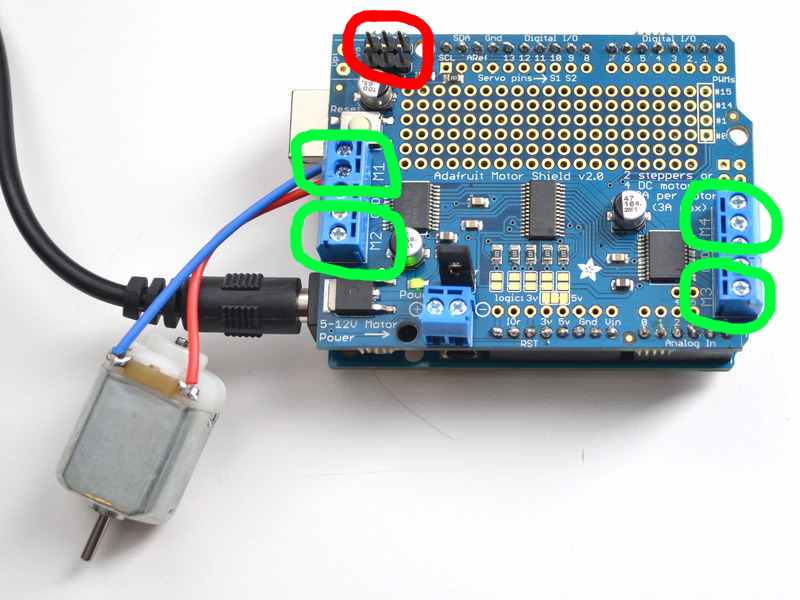
To control them from the Arduino (through the motor shield), you will have to connect them to the M1 and M2 motor ports instead of the servo port (see picture):
Use one of the ports circled in Green (the screw terminals), not the 3-pin headers circled in Red.
You can use any 2 of the 4 motor ports (m1, m2, m3, or m4). You will make mention of this in the Arduino code.
Also, you will need to make sure that you have the correct AF motorshield library - The library for the AF motorshield used in my book is not the one you need.
Follow the instructions on this page (if you haven't already done this):
https://learn.adafruit.com/adafruit-motor-shield-v2-for-arduino/install-software
Then upload this code:
This code sets up the 2 motors on M1 and M2 - you can change those numbers at the top of the file where the motors are assigned if you for instance want to use M1 and M3 or whatever.
This should work... if not, let me know what happens and we can go from there.
Also, if you connect Digital pin 2 (D2) to the GND pin when powering up the Arduino, it will start printing values to the serial monitor for you to debug with.
Cheers,
JD
Success, JD! But with one qualification. Recall that your book described the linebot project using 5 sensors. The new Linus script you uploaded only described logic for 3 sensors. Unfortunately my circuit board has 5 sensors soldered across the board, with 4 or 5 circuit board holes spaced between them. I tested your script by running off just the A0, A2 and A4 sensor, but the linebot doesn't really "capture the black line" very well and veers off track pretty easily. I'm using standard electrical black tape that looks to be about 3/4" wide. Can you update your script to work with 5 sensors? Or is there an easy way to copy the sensor code from the original script into this latest script you've created?
Incidentally, just to let others know, I had tremendous troubleshooting difficulties until I upped my battery count to 8x1.5v cells.
Thanks for all you help. - Don

