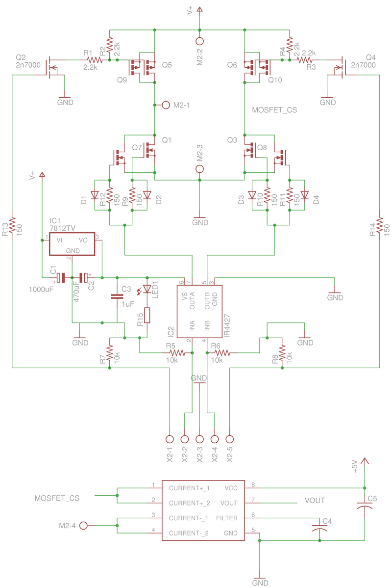
This motor-driver is an H-bridge circuit that was designed to drive a single DC motor at up to 30amps at 24vdc. It incorporates a simple design utilizing parallel mosfets to allow a higher amperage rating and requires 4 wires to control each bridge, 2 digital and 2 PWM capable.
You can find the files to build one here: https://sites.google.com/site/arduinorobotics/home/chapter8
The high-side switches in each bridge are high-power P-channel mosfets intended to be digitally controlled (On or Off) using a set of small n-channel signal transistors (2n7000). One signal transistor can supply up to 200mA of current to each set of P-channel mosfets to turm them On, while 2.2k pull-up resistors keep them turned off when not in use. While the schematic shows the signal transistors as 2n7000 n-channel mosfets, you can substitute these for standard 2n2222 BJT signal transistors as they will both fit.
The low-side switches are high-power N-channel mosfets controlled by a PWM signal from a microcontroller which is passed through a mosfet driver IC (TC4427) to buffer the signals making ultrasonic PWM frequencies possible (32kHz tested). The low-side switches have gate resistors to ensure even current levels to each mosfet from the driver IC, and shottkey diodes at each gate to close the mosfet more quickly, which will allow for higher switching speeds. Each signal input is grounded thorugh a pull-down resistor to ensure that all switches are turned off when not controlled by the microcontroller.
There is also a linear 12v regulator (LM7812) to provide a stable voltage for the onboard mosfet driver IC. The power supply also incorporates a few decoupling capacitors and a bulk capacitor on the 12v output to provide a buffer for the mosfet driver IC.
Lastly, I added an optional current sensor IC (ACS714) on the rear of the board (surface mount chip) to interface witth the microcontroller to provide overcurrent protection during use. By connecting this IC inline with one of the motor outputs, it can read the current up to 30Amps in either direction, and will output an analog voltage proportional to the current level. The analog signal can be read by the microcontroller that is commanding the H-bridge. This IC also requires a few decoupling capacitors and a +5v signal that is provided by the microcontroller.
Below is the schematic of the circuit:
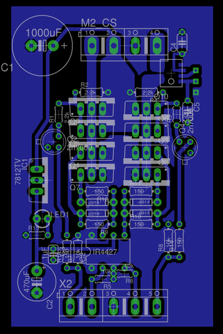
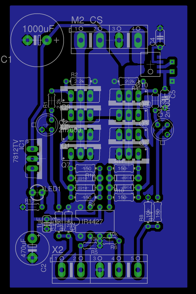
And the Board file (Eagle Cad) for one H-bridge:
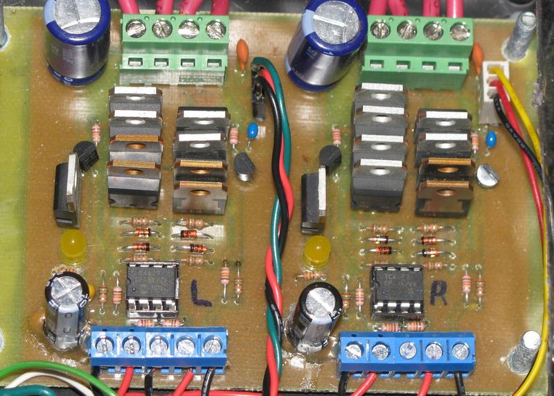
And a picture of my finished Dual H-bridge board:
Here is some sample code for Arduino to both run the board using an R/C signal, and to read the current sensors and implement overcurrent protection:
// This is the main code, it should run on the Arduino.

// Read PPM signals from 2 channels of an RC reciever and convert the values to PWM in either direction.

// digital pins 3 & 11 provide PWM control motor1, digital pins 9 & 10 provide PWM control motor2.

// DP 12 and 13 are neutral indicator lights.

// DP 2 and 6 are inputs from the R/C receiver.

// JDW 2010


// leave pins 0 and 1 open for serial communication


int ppm1 = 2;

int ppm2 = 6;


int motor1_BHI = 7;

int motor1_BLI = 3;  // PWM pin

int motor1_ALI = 11;  // PWM pin

int motor1_AHI = 8;


int motor2_BHI = 5;

int motor2_BLI = 10;   //PWM pin

int motor2_ALI = 9;  //PWM pin

int motor2_AHI = 4;


int ledPin1 = 12;

int ledPin2 = 13;


int current_sense_1;

int current_sense_2;


int current_limit = 25;  // sets the amperage limit that when exceeded on either motor, tells the motor driver to cut power to both motors for 1 second.


unsigned int servo1_val;

int adj_val1;

int servo1_Ready;


unsigned int servo2_val;

int adj_val2;

int servo2_Ready;


unsigned int servo3_val;

int adj_val3;

int servo3_Ready;


int deadband_high = 275;

int deadband_low = 235;


int pwm_ceiling = 256;

int pwm_floor = 255;


// You can adjust these values to calibrate the code to your specific radio - check the Serial Monitor to see your values.

int low1 = 1100;

int high1 = 1900;

int low2 = 1100;

int high2 = 1900;


void setup() {


  TCCR1B = TCCR1B & 0b11111000 | 0x01; // change PWM frequency on pins 9 and 10 to 32kHz

  TCCR2B = TCCR2B & 0b11111000 | 0x01; // change PWM frequency on pins 3 and 11 to 32kHz


  Serial.begin(9600);


  //motor1 pins

  pinMode(motor1_ALI, OUTPUT);

  pinMode(motor1_AHI, OUTPUT);

  pinMode(motor1_BLI, OUTPUT);

  pinMode(motor1_BHI, OUTPUT);


  //motor2 pins

  pinMode(motor2_ALI, OUTPUT);

  pinMode(motor2_AHI, OUTPUT);

  pinMode(motor2_BLI, OUTPUT);

  pinMode(motor2_BHI, OUTPUT);


  //led's

  pinMode(ledPin1, OUTPUT);

  pinMode(ledPin2, OUTPUT);


  //PPM inputs from RC receiver

  pinMode(ppm1, INPUT);

  pinMode(ppm2, INPUT);


}


void pulse(){


  servo1_val = pulseIn(ppm1, HIGH, 20000);


  if (servo1_val > 800 && servo1_val < 2200){

    servo1_Ready = true;

  }

  else {

    servo1_Ready = false;

    servo1_val = 1500;

  }


  servo2_val = pulseIn(ppm2, HIGH, 20000);


  if (servo2_val > 800 && servo2_val < 2200){

    servo2_Ready = true;

  }

  else {

    servo2_Ready = false;

    servo2_val = 1500;

  }


}


void loop() {


  // read current sensors on motor-controller

  current_sense_1 = analogRead(1);

  current_sense_2 = analogRead(2);


  //////// determine which direction each motor is spinning


  if (current_sense_1 > 512){

    current_sense_1 = current_sense_1 - 512;

  }

  else {

    current_sense_1 = 512 - current_sense_1;

  }


  if (current_sense_2 > 512){

    current_sense_2 = current_sense_2 - 512;

  }

  else {

    current_sense_2 = 512 - current_sense_2;

  }


  //////// adjust the directional value into Amperes by dividing by 13.8


  current_sense_1 = current_sense_1 / 13.8;

  current_sense_2 = current_sense_2 / 13.8;


  //////// if either Ampere value is above the threshold, stop both motors for 1 second


  if (current_sense_1 > current_limit || current_sense_2 > current_limit){

    m1_stop();

    m2_stop();

    delay(1000);

  }


  pulse(); // gather pulses from the R/C


  if (servo1_Ready) {


    // channel 1

    adj_val1 = map(servo1_val, low1, high1, 0, 511);

    adj_val1 = constrain(adj_val1, 0, 511);


    if (adj_val1 > 511) {

      adj_val1 = 511;

    }

    else if (adj_val1 < 0) {

      adj_val1 = 0;

    }

    else {

    }


    if (adj_val1 > deadband_high) {

      m1_forward(adj_val1 - pwm_ceiling);

    }

    else if (adj_val1 < deadband_low) {

      m1_reverse(pwm_floor - adj_val1);

    }

    else {

      m1_stop();

    }

  }

  else {

    m1_stop();

  }


  if (servo2_Ready) {


    // channel 2

    adj_val2 = map(servo2_val, low2, high2, 0, 511);

    adj_val2 = constrain(adj_val2, 0, 511);


    if (adj_val2 > 511) {

      adj_val2 = 511;

    }

    else if (adj_val2 < 0) {

      adj_val2 = 0;

    }

    else {

    }


    if (adj_val2 > deadband_high) {

      m2_forward(adj_val2 - pwm_ceiling);

    }

    else if (adj_val2 < deadband_low) {

      m2_reverse(pwm_floor - adj_val2);

    }

    else {

      m2_stop();

    }


  }

  else {

    m2_stop();

  }


  Serial.print("M1 Amps =   ");

  Serial.print(current_sense_1);

  Serial.print("  ");


  Serial.print("M2 Amps =   ");

  Serial.print(current_sense_2);

  Serial.print("  ");


  Serial.print("channel 1:  ");

  Serial.print(adj_val1);

  Serial.print("  ");


  Serial.print("channel 2:  ");

  Serial.print(adj_val2);

  Serial.print("  ");


  Serial.print("Switch Value:  ");

  Serial.print(servo3_val);

  Serial.println("  ");


}


void m1_forward(int m1_speed){

  digitalWrite(motor1_AHI, LOW);

  digitalWrite(motor1_BLI, LOW);

  digitalWrite(motor1_BHI, HIGH);

  analogWrite(motor1_ALI, m1_speed);

  digitalWrite(ledPin1, LOW);

}


void m1_reverse(int m1_speed){

  digitalWrite(motor1_BHI, LOW);

  digitalWrite(motor1_ALI, LOW);

  digitalWrite(motor1_AHI, HIGH);

  analogWrite(motor1_BLI, m1_speed);

  digitalWrite(ledPin1, LOW);

}


void m2_forward(int m2_speed){

  digitalWrite(motor2_AHI, LOW);

  digitalWrite(motor2_BLI, LOW);

  digitalWrite(motor2_BHI, HIGH);

  analogWrite(motor2_ALI, m2_speed);

  digitalWrite(ledPin2, LOW);

}


void m2_reverse(int m2_speed){

  digitalWrite(motor2_BHI, LOW);

  digitalWrite(motor2_ALI, LOW);

  digitalWrite(motor2_AHI, HIGH);

  analogWrite(motor2_BLI, m2_speed);

  digitalWrite(ledPin2, LOW);

}


void m1_stop(){

  digitalWrite(motor1_BHI, LOW);

  digitalWrite(motor1_ALI, LOW);

  digitalWrite(motor1_AHI, LOW);

  digitalWrite(motor1_BLI, LOW);

  digitalWrite(ledPin1, HIGH);

}


void m2_stop(){

  digitalWrite(motor2_BHI, LOW);

  digitalWrite(motor2_ALI, LOW);

  digitalWrite(motor2_AHI, LOW);

  digitalWrite(motor2_BLI, LOW);

  digitalWrite(ledPin2, HIGH);

}
// END CODE