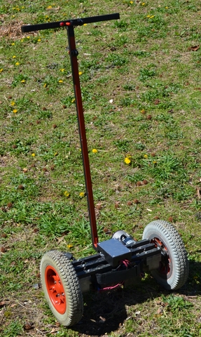
The Seg-bot is a DIY segway clone that costs around $500 to build. It will attempt to keep the rider upright at 0 degrees (level), so if you lean forward it will travel forward to correct its position - the farther you lean, the faster it will go to correct itself. It weighs about 80-90lbs with batteries and motors installed so it can be dangerous if you are not careful, but once you learn to ride it, it is as stable as you are and very easy to maneuver.
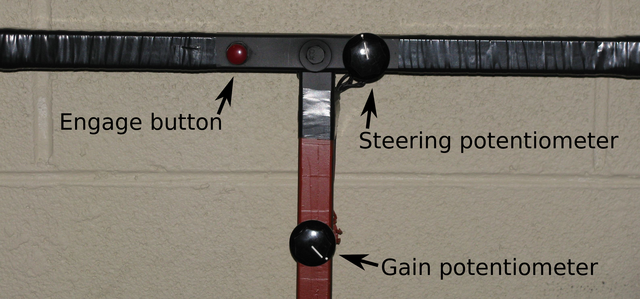
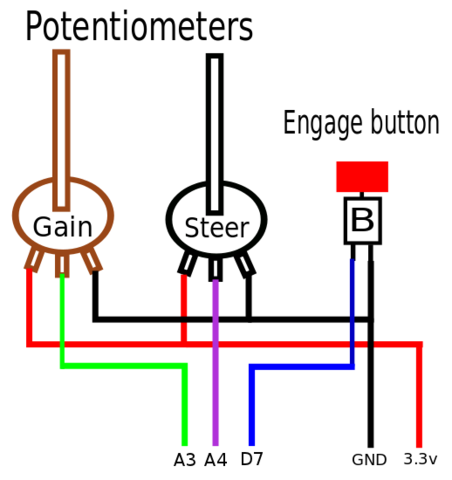
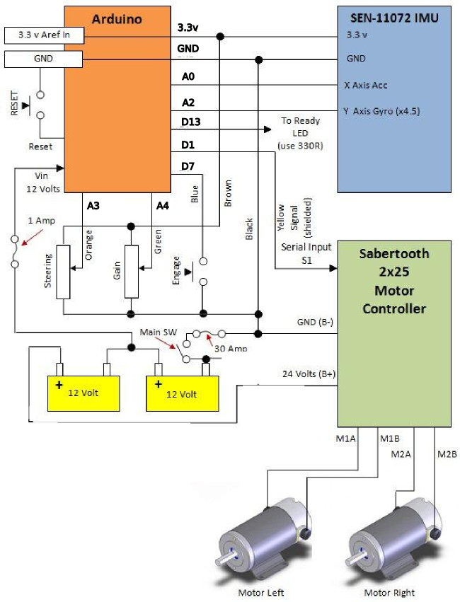
The Seg-bot is controlled with an Arduino microcontroller, which is connected to two sensors - a gyroscope and an accelerometer. The gyro and accelerometer measure the angle of the Seg-bot as it tilts from front to back on the wheels. The Arduino can then use that angle measurement to determine how fast and in which direction it should command the motors. Since these motors are power wheelchair gear motors, they are quite large and cannot be driven directly by the Arduino, so I used a Sabertooth 2x25 motor controller to feed power to the motors. A set of 12-Volt, 12Amp/Hour rechargeable batteries lend plenty of power to the Sabertooth, so it will travel for quite a while. Lastly, in order to control the Seg-bot I added a steering potentiometer and an engage button to the handle-bar.
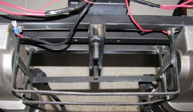
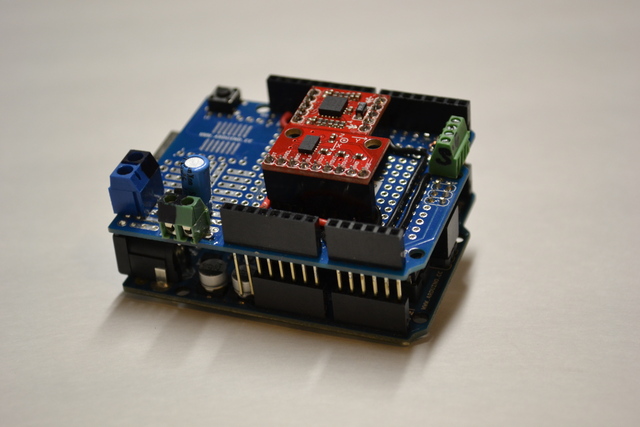
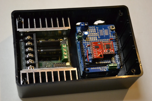
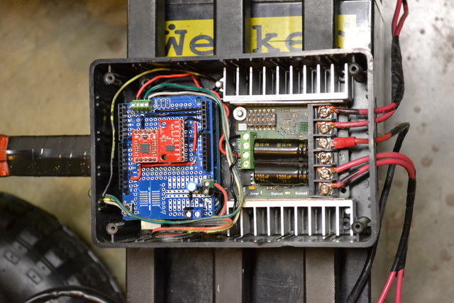
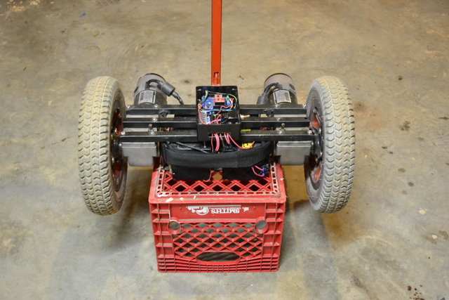
Seg-bot brain with sensors and motor-controller:

To be honest, I kind of thought this project would end up a wash, where I had a half-built useless robot base that moved but wouldn't balance with me on it....
That is not at all what happened. With some coding help from by buddy Josh, I was able to get it working from start to finish in about 1 month - and it was rideable from the very first try! I wrote some code on the Arduino to measure the angle of both sensors and then combine them into a single filtered angle (more on this later), so I was able to test this on the Arduino by reading the values back on my computer screen.. so after a few weeks of tweaking this, I was comfortable that it would work in practice.
Check out a video of my first test-drive:
Of course, the Seg-bot has gotten plenty of love since then with quite a bit of tweaking, some potentiometer re-arrangement, an over-tilt cutoff, auto-balancing re-engage, and more features coming.
Sparkfun.com has discontinued the Razor 6DOF IMU (accelerometer + gyroscope), so I decided to find a replacement - when I did, they discontinued that and the next one. So, my current plan is to obtain a batch of sensors from them soon and sell them on this site so you won't have to go searching the internets.
In the mean time, here are a few options for replacement sensors:
Gyroscope: http://www.sparkfun.com/products/10099
Accelerometer: http://www.sparkfun.com/products/9269
Using this option, you can use the same code as the book, but you must run separate power and GND signals to each sensor. The Gyro is "retired" from Sparkfun's lineup, but you can still find stores that sell them if you search Google for "LPY530AL breakout" - several diy websites still have some of these from Sparkfun in stock.
I just finished writing some code for the inexpensive MMA7361 3-axis accelerometer ($12 from Sparkfun), so you can use it instead of the ADXL335 ($24). I have not yet however had a chance to work with a different Gyroscope since they discontinued making the LPY530al breakout boards. I would like to try the less sensitive version of the original gyro (30 degree/sec instead of 300 degree/sec), which Sparkfun still carries:
Gyro: http://www.sparkfun.com/products/9424
This would require some code tweaking to get it calibrated correctly, but it should not be too difficult for anyone who knows how to troubleshoot and use the Arduino Serial monitor to check the sensor values.
This board uses the same accelerometer as the original Razor 6DOF, but a different gyro that measures 500 degrees/second vs 300, but it works just as well. I rewrote the code to auto-calibrate both sensors in the Setup function each time the Arduino is turned on. This way, you don't have to try to calibrate your sensors. This means that whatever angle the Seg-bot is at when you turn it on, will be the angle that it assumes to be "level".
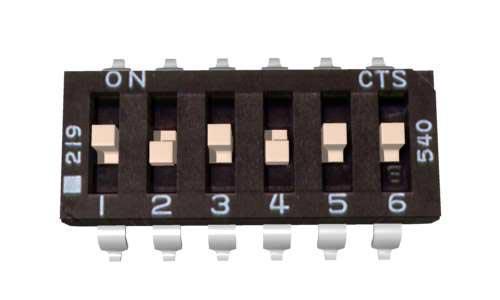
I also did away with using the SoftwareSerial library which slows the loop cycle down considerably - instead, I wrote the sketch so that if you have pin 12 grounded during startup, the sketch will boot up into "debugger" mode and will print the sensor values to the serial monitor. If pin 12 is left alone, the Segbot will operate normally and write serial values to the Sabertooth motor-controller. If you start the Arduino in debug mode, you should disconnect the Serial wire from pin D1 on Arduino to S1 input on the Sabertooth to avoid sending strange values to the motor-controller.
Here is a link to the new sensor:
http://www.sparkfun.com/products/11072
And here is a link to the Github repo with each version of the code:
https://github.com/johndavid400/Segbot
Remember to check the pin assignments in the code against your actual input connections to make sure everything is correct.

(Click on the icon below)