Chicken Coop
By: johndavid400
What is this?
This project is an automated chicken coop door opener used to open our chicken coop door every morning and close it again every night. It uses the light from the sun to determine when to open and close, and infrared sensors mounted to the door to determine its position.
Background:
If you have ever taken care of chickens, you know that they are not really able to protect themselves... at all. So you basically have to provide a place for them to "roost" every night to keep them being eaten by the neighborhood racoon, possum, rat, hawk, dog, etc. Well, not only can they not defend themselves, but they also wake up at the crack of dawn and start itching to get outside to find bugs and do other chicken things. If you have a rooster, then you will know exactly when they get up every morning and if you don't let them out right away, they will crow until you do. On the flip side, when night comes and it gets dark, chickens go to their place of safety to roost. If you forget to close the door to their coop one night, you might just wake up to one less chicken the next morning.
To alleviate my wife from having to get up early each morning and open a chicken door in the cold or remember every night to go outside (again usually cold) to close their door, I decided to make an Arduino handle that for her.
Lift Motor
To get started, I bought a motor that had enough torque to lift a plywood door. I started by buying and taking apart an old 12v drill from the thrift-store to use it's motor and gearbox. This had plenty of power to lift the door, but even on its "slow" setting was too fast to stop lifting the door at the right time. I tried several different methods of driving it, including sending pulses every few seconds to lift just a little bit each time until it got to the top, but it proved to be just too dang fast which resulted in lifting the door too high, which would break the cable that it used to lift the door. I realized that I simply had the wrong motor.
Next, I went with a small 380 size motor that came out of a printer and had a super high gear ratio that made it extremely slow moving and had lots of torque (for its size). Unfortunately, it did not have enough torque to lift the wooden door and I had to scrap it also.
Then I found a decent sized gear motor on Amazon that was used to move a powered seat in a car. The motor itself is nearly the size of a soda can, about 2.5" in diameter and about 4" long. It has a worm-gear that spins at about 190rpm at 12v and has a no load current rating of 1.5amps, stall current of 25amps. This motor has more than enough torque to lift the chicken coop door, but also only has a $15 price tag.
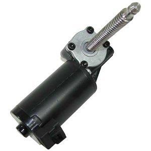
http://www.amazon.com/12Vdc-Right-Angle-Drive-Electric/dp/B005IR1NBA/ref=pd_sim_sbs_indust_1
Motor-controller
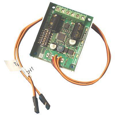
To power the motor, I dabbled with a few cheap implementations of an H-bridge using spare parts, but none were reliable enough for a set-and-forget application like this. So I went with an old Sabertooth 2x12 R/C motor-controller that handles up to (2) DC motors at 12amps continuous each and 20amp peaks. The only problem is that the Sabertooth 2x12 R/C can only be controlled using R/C pulse signals, as opposed to the standard Sabertooth that comes with the option to use R/C, analog, or serial connection to control the motors. While this is not the ideal way to control motors in a system that has no R/C equipment... it does work and I already had it laying around so there.
Sensors
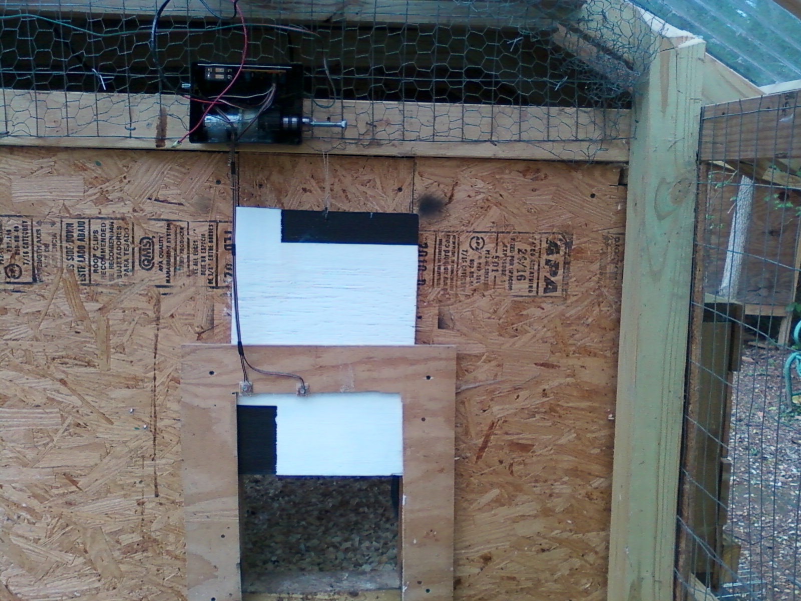
You might be wondering how the Arduino knows when to open/close the door, and whether the door is open or closed at any given time. To determine the position of the door, I could have used mechanical switches mounted to the top and bottom of the door, but I decided to use infrared sensors to measure the reflectiveness of the door - to do this, I had to paint the door solid white and then paint 2 black boxes on the front. The white base coat is used to give the IR sensors a default value to read - white is highly reflective, so the IR detector will produce a very high analog value when being read by the Arduino. Likewise, the black paint is not reflective at all and will produce a very low analog value when being read by the Arduino.
The black boxes are painted on the top and bottom of the chicken door, the bottom box is on the left side of the door and the top box is on the right side of the door. The black boxes serve as end points for the infrared sensors to read and know when to stop raising or lowering the door. There are 2 infrared emitter/detector pairs mounted to the door frame - the one on the left is always reading the white paint unless the door is fully raised, in which case the left IR sensor will read the black box and know that the door is open. The sensor on the right side is always reading the white paint unless the door is fully lowered, in which case it will read the black box and know that the door is closed.
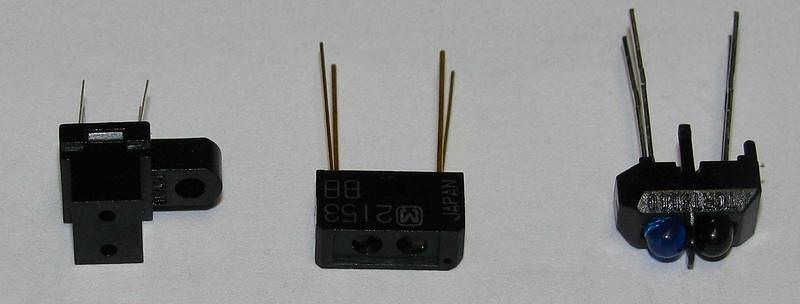
Here are some different IR emitter/detector pairs (I used the one in the center for this project):
To determine whether or not the door should be open or closed, I used a simple LDR sensor (light dependent resistor) from Radio Shack to read the amount of sunlight at any given time. This sensor is mounted in the roof of the chicken run (it has clear polycarbonate roofing) so it has a clear view of the sky. When the light level gets too high, the Arduino knows that it is daytime and it should open the door - so it will make sure the left (up) sensor is reading it's black box and if not, raise the door until it does. At night, when the light level falls below the threshold, the Arduino then knows it is night time and that it should close the door. So at this point it tries to make sure the right (down) sensor is reading it's black box and if not, lower the door until it does.
This is pretty simple, but requires some strategic placement of the black painted boxes on the door, in order to set how far the door opens and closes. All of the sensors, both Infrared emitter/detector pairs and the light sensor, plug into the Arduino's Analog ports and are read using the analogRead() command.
Control Box
While the motor, both IR sensors, and the LDR sensor are mounted around the chicken coop, the Arduino and motor-controller are both housed inside of a plastic project box from Radio Shack to keep them from getting water or other debris on them. The project box initially housed the motor as well, but it was removed for more flexibility to mount everything. There are times when you might want to close the chicken door manually instead of using automatic mode, so I added a simple SPST switch to switch between auto and manual modes, and added 2 buttons to allow for a manual raise and lower feature. When the switch is flipped, the door can be controlled using the 2 buttons.
Adjust Motor Speed and Light Threshold
In addition to the manual/auto selector, I also decided that it might be useful to be able to adjust the speed of the motor on the fly without reprogramming the Arduino. So I added a simple potentiometer to determine the 0-100% speed of the motor that can be changed at any time. This is useful as you can slow the door down to a safe speed so that it does not become a chicken guillotine.
Likewise, I thought it would be useful to be able to adjust the threshold of the light sensor. I again used a simple potentiometer to set the analog value threshold - this threshold determines at what point the Arduino considers Day and what it considers Night. You can adjust this on the fly as well, which I do by going out to the chicken coop at sundown when the chickens are ready for bed... and then turn the sensitivity knob down until the door decides to close. Now if left in this position, the door should open the next morning at the same light level as when it closes. This roughly translates to about 5-6am open time and about 6-7pm closing time for me.
Here is the Arduino code for this project... you would have to change the motor control commands if using a different motor-controller:
// Automated Chicken coop door
// jdw - may 2012
// motor driven by Sabertooth 2x12 RC on pin D6
// bottom pot = A5, top pot = A4
// bottom button = D3, top button = 2, switch = 4
// top IR sensor = A0, bottom IR sensor = A1
// light sensor = A2

// Sabertooth 2x12 RC control wire - connect to D6
int door_motor_pin = 6;
// variables for door top Infrared sensor - connect to A0
int ir_top = 0;
int ir_top_val;
int ir_top_sum = 0;
// variables for door bottom Infrared sensor - connect to A1
int ir_bottom = 1;
int ir_bottom_val;
int ir_bottom_sum = 0;
// variables for LDR (light sensor) - connect to A2
int ldr = 2;
int light_val;
int light_sum = 0;
// variables for aux potentiometers - connect to A4 and A5
int pot1 = 5;
int pot2 = 4;
int dawn_dusk = 25;
// variables for red button - connect to D2
int button_red = 2;
int button_red_val;
// variables for black button - connect to D3
int button_black = 3;
int button_black_val
// variables for toggle switch - connect to D4
int toggle_switch = 4;
int toggle_switch_val;
// extra variables
int ir_threshold = 150;
boolean closed = 0;
boolean daytime = 0;
boolean automatic = 0;

void setup(){
  Serial.begin(9600);
  pinMode(door_motor_pin, OUTPUT);
  pinMode(ir_top, INPUT);
  pinMode(ir_bottom, INPUT);
  pinMode(pot1, INPUT);
  pinMode(pot2, INPUT);
  pinMode(ldr, INPUT);
  pinMode(button_red, INPUT);
  digitalWrite(button_red, HIGH);
  pinMode(button_black, INPUT);
  digitalWrite(button_black, HIGH);
  pinMode(toggle_switch, INPUT);
  digitalWrite(toggle_switch, HIGH);
  door_stop();
  delay(500);
}

void loop(){

  read_sensors();

  if (automatic){
    if (daytime){
      if (ir_top_val > ir_threshold){
        door_up;
      }
      else {
        door_stop();
      }
    }
    else {
      if (ir_bottom_val > ir_threshold){
        door_down;
      }
      else {
        door_stop();
      }
    }
  }
  else {
    if (button_red_val == HIGH && button_black_val == LOW){
      door_up();
    }
    else if (button_red_val == LOW && button_black_val == HIGH){
      door_down();
    }
    else {
      door_stop();
    }
    Serial.print("LDR: ");
    Serial.print(light_val);
    Serial.print("  Top: ");
    Serial.print(ir_top_val);
    Serial.print("  Bottom: ");
    Serial.print(ir_bottom_val);

    Serial.print("  DD: ");
    Serial.print(dawn_dusk);
    Serial.print("  speed: ");
    Serial.print(motor_speed);

    Serial.println("");
  }
}

void read_ir_sensors(){
  for (int x = 0; x < 10; x++){
    ir_top_sum += analogRead(ir_top);
    delay(10);
  }
  ir_top_val = ir_top_sum / 10;
  ir_top_sum = 0;

  for (int x = 0; x < 10; x++){
    ir_bottom_sum += analogRead(ir_bottom);
    delay(10);
  }
  ir_bottom_val = ir_bottom_sum / 10;
  ir_bottom_sum = 0;
}

void read_ldr(){
  for (int x = 0; x < 10; x++){
    light_sum += analogRead(ldr);
    delay(10);
  }
  light_val = light_sum / 10;
  light_sum = 0;

  if (light_val > dawn_dusk){
    daytime = true;
  }
  else {
    daytime = false;
  }
}

void read_inputs(){
  automatic = digitalRead(toggle_switch);
  button_red_val = digitalRead(button_red);
  button_black_val = digitalRead(button_black);

  dawn_dusk = analogRead(pot2);
  motor_speed = map(analogRead(pot1), 0, 1023, 0, 500);
}

void read_sensors(){
  read_ir_sensors();
  read_ldr();
  read_inputs();
}

void door_up(){
  digitalWrite(door_motor_pin, HIGH);
  delayMicroseconds(1500 + motor_speed);
  digitalWrite(door_motor_pin, LOW);
}

void door_down(){
  digitalWrite(door_motor_pin, HIGH);
  delayMicroseconds(1500 - motor_speed);
  digitalWrite(door_motor_pin, LOW);
}

void door_stop(){
  digitalWrite(door_motor_pin, HIGH);
  delayMicroseconds(1500);
  digitalWrite(door_motor_pin, LOW);
}


So if you needed to change the command issued to make the motor go forward, you would change this command:

void door_up(){
  digitalWrite(door_motor_pin, HIGH);
  delayMicroseconds(1500 + motor_speed);
  digitalWrite(door_motor_pin, LOW);
}to be something like this:

void door_up(){
  analogWrite(door_motor_pin, motor_speed);
}