This tutorial will attempt to simply a commonly used digital output method that might be a bit confusing, PWM. Firstly we must understand that pulse width modulation is a type of digital signal so it can only be either 0v when LOW or 5v when HIGH (on an Arduino). The tricky part is that the digital signal is switching from LOW to HIGH really quickly, usually too fast for you to notice - the result however is that of an Analog output signal and can appear to be anywhere between 0v and 5v. To illustrate what is happening, we will examine the most basic Arduino sketch possible, the "Blink" sketch.
copied from the Arduino Playground: http://arduino.cc/en/Tutorial/Blink
// Pin 13 has an LED connected on most Arduino boards.
// give it a name:
int led = 13;
int delay_time = 1000;

// the setup routine runs once when you press reset:
void setup() {
  // initialize the digital pin as an output.
  pinMode(led, OUTPUT);
}

// the loop routine runs over and over again forever:
void loop() {
  digitalWrite(led, HIGH);   // turn the LED on (HIGH is the voltage level)
  delay(delay_time);               // wait for a second
  digitalWrite(led, LOW);    // turn the LED off by making the voltage LOW
  delay(delay_time);               // wait for a second
}
Basically, this is a sketch that turns the LED on pin 13 HIGH for 1 second, then LOW for 1 second. This is a very basic form of PWM that can show what is happening if you slowed down time a bit. During this sketch there is a 1 second delay between the switching of the LED's state, so you can see the blinking quite obviously. What happens when you change the "delay_time" variable in the sketch from 1000 milliseconds to 500 milliseconds? (try it). Now try 100, then 10, and finally 1. See how the lower you get, the faster the blinking occurs? At some point, the LED just starts to look like it is faded and only halfway On - this is because the blinking is so fast that your eyes are no longer able to detect it.
Also notice that we set the "delay_time" variable to be the same for both the HIGH and the LOW times of the LED. This means that no matter what value you choose, you are going to be turning the LED On for just as long as you are turning it Off - it is HIGH for 50% of the time, and LOW for the other 50%. The signal that is generated from this code, would be a (nearly) perfect square wave, where the signal is symmetrical when being read by a digital signal analyzer (oscilloscope).
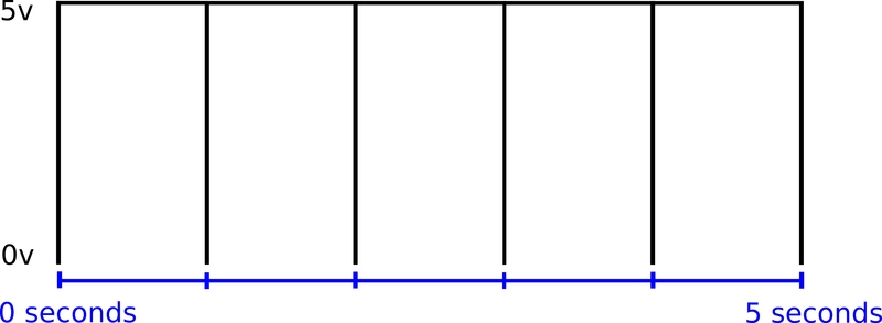
This is a graph of what the signal from the sketch above would look like on an oscilloscope:
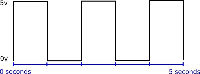
Notice that each HIGH and LOW pulse takes up an entire second each! This means that 1 "cycle" takes exactly 2 seconds - a cycle is one complete HIGH then LOW pulse. In this case, you would only see 1/2 of a cycle per second. The cycle speed is referred to as the "frequency" of the signal, because PWM signals generally maintain a constant frequency throughout their operation. Frequency in digital signals is measured in Hertz or Hz (which is the number of cycles per second) and the above signal would only be 0.5 Hz since it takes 2 seconds to complete 1 cycle. So what would a perfect 1 Hz signal look like?
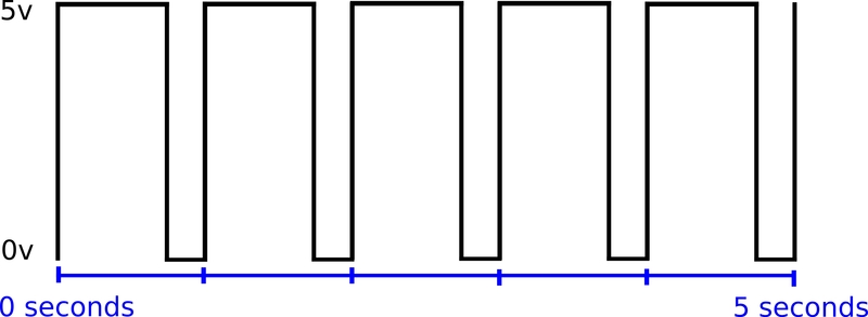
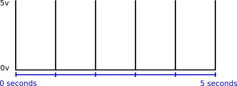
If you changed the delay_time variable to 500 milliseconds per half-cycle, the combined HIGH and LOW time of each cycle would total 1000 milliseconds or 1 second:

If you tried to upload a 500 millisecond delay_time to your Arduino, you might notice that 1 blink per second is pretty noticeable and not at all what you typically think of when dealing with PWM - but that is only because 1 Hz is just about the slowest PWM you are going to ever try. So to move one step forward, the Arduino has 6 pins that are capable of true PWM output, digital pins: 3, 5, 6, 9, 10, and 11. These pins are dedicated as PWM pins, because the Arduino has 3 system timers that are ticking all the time that the Arduino is running and the speed at which they are running is based on the Arduinos 16Mhz oscillator chip (yes, that is 16 megahertz or 16,000,000 hertz). While the speed of all 3 timers is capable of being changed, the important thing to know right now is that the Arduino is preset to output a 1000 Hz PWM frequency on pins 5 and 6 which are tied to the main system timer (this timer is what the delay(), millis(), and micros() values are based on), while the other PWM pins 3, 9, 10, and 11 run at a default speed of 500 Hz. As you might guess, 500 Hz simply means that there are 500 complete cycles per second and 1KHz means there are 1000 cycles per second. If you calculate the actual time of each complete cycle, you would end up with the following.
For 500 Hz:
1000 milliseconds (1 sec) / 500 cycles = 2 milliseconds per cycle
For 1 KHz:
1000 milliseconds (1 sec) / 1000 cycles = 1 millisecond per cycle
As you can see, we jumped from seconds of delay, to milliseconds of delay! This is significant because if you put a 1 millisecond total cycle time, you will not notice any blinking of the LED, instead it will appear as though it is only half way turned On. Now consider that most loads that utilize PWM are driven between 1 kHz to 32 kHz! 32,000 cycles per second only leaves 32 microseconds per cycle - again, that is microseconds which is equivalent to 1,000,000th of one second. Obviously at 32 kHz, you would not notice any blinking at all. And if it is not obvious yet, to change the frequency of a PWM signal, we are basically changing the length of each HIGH/LOW cycle in the signal.
So we have discussed the frequency of a PWM signal, but every signal that we have generated so far has been 50% HIGH and 50% LOW. This means that regardless of what frequency we choose, the actual time that the LED is turned on will never exceed 50% - or you might say 50% of its total available brightness. To change the brightness of the LED at any frequency, we need to adjust something else - we call this the "duty-cycle".
The duty-cycle is simply the ratio of how long each cycle is HIGH versus how long it is LOW. From the example above, we have a signal that is always 50% HIGH and 50% LOW every cycle. To change the duty-cycle of the PWM signal, we would only need to divide each cycle time into something other than 50/50. For instance to raise the duty-cycle of the signal we have been working with to say 75%, we would need to make the HIGH delay_time a tad bit longer than the LOW delay_time.
An example would be:
// Pin 13 has an LED connected on most Arduino boards.
// give it a name:
int led = 13;
int high_delay_time = 750;
int low_delay_time = 250;

// the setup routine runs once when you press reset:
void setup() {
  // initialize the digital pin as an output.
  pinMode(led, OUTPUT);
}

// the loop routine runs over and over again forever:
void loop() {
  digitalWrite(led, HIGH);   // turn the LED on (HIGH is the voltage level)
  delay(high_delay_time);               // wait for a second
  digitalWrite(led, LOW);    // turn the LED off by making the voltage LOW
  delay(low_delay_time);               // wait for a second
}
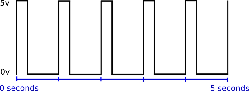
Notice here that we simply separated the delay_time variable into two different variables: "high_delay_time" and "low_delay_time". Now we can separately set how long each cycle is going to be HIGH and how long each cycle is going to be LOW. Keep in mind that the sum of your HIGH and LOW delay times will determine the frequency of the signal, so make sure that if you add them together that they equal the total desired cycle time (1 millisecond in this example). When we set the HIGH delay time to be 750 milliseconds and the LOW delay time to be 250 milliseconds, the total is still 1000 milliseconds (1 second), but the signal will be HIGH for 75% of the time and LOW for 25% of the time. We have now maintained the 1 Hz frequency but increased the duty-cycle from 50% to 75%. If you were to increase the frequency and maintain the 75% duty cycle, you would notice that the LED does not blink at all, but also appears to be slightly brighter than it did at 50% duty-cycle.
Here is a graph of the same 1 Hz signal at 75% duty-cycle:
The same is true if we go in the opposite direction and reduce the duty-cyle to 25% from 50%. We would change the HIGH delay time to 250 milliseconds and the LOW delay time to 750 milliseconds which would mean the signal was only HIGH for 25% of the time.
Here is the same 1 Hz signal with a 25% duty-cycle:
I'm hoping that at this point, the relationship between frequency and duty-cycle make sense to you... or at least how they are different. Unfortunately, trying to calculate your own PWM frequency and duty-cycle is not much fun. Luckily, the Arduino takes care of this for you if you use one of the dedicated PWM pins we talked about earlier (Digital pins: 3, 5, 6, 9, 10, 11). We also discussed how the Arduino has a default PWM frequency for each output (which can be changed) - the only thing needed is for you to determine the duty-cycle of the signal you wish to send (0%-100%). Using the analogWrite(pin, duty-cycle) command, you can easily write to any of the PWM output pins on the Arduino with one line of code. The only caveat is that the number you pass in must be an 8-bit number between 0 and 255 - where 0 is equal to 0% duty-cycle and 255 is equal to 100% duty-cycle.
The following code snippets might help you understand this better.
To send a full 5v signal (100%) through the PWM pin D3, you would do:
analogWrite(3, 255);
Here is a graph of 100% duty-cycle:
To send a 2.5v signal (50%) through the PWM pin D3, you would do:
analogWrite(3, 128);
To send a 0v signal (0%) through the PWM pin D3, you would do:
analogWrite(3, 0);
Here is a graph of 0% duty-cycle:
Notice that even if the signal is 0%, it still goes to 5v for a split second just because it has to in order to complete the cycle. Don't worry about whether or not you are reaching a true 100% duty-cycle, your system is not likely to be 100% efficient anyways.
As for the frequency that you are operating at... the minimum Arduino default is 500 Hz which is plenty high of a speed such that you won't notice any blinking from LED's or other resistive loads. When driving motors from a 500 Hz PWM signal, you might notice a whining noise coming from the motors when you apply power... this is because though your eyes are only good for about 30 frames per second and the 500 Hz does not appear to be blinking when driving an LED, your ears can detect frequencies quite differently and can notice any frequency below 24kHz - 32kHz. Above this range and you will notice a completely silent motor operation. The Arduino is capable of PWM frequencies up to 64kHz.
Why not just use 64kHz all the time? Well, generally the Arduino can only supply around 40 milliamps of current from any output pin, so if you are going to drive a motor or other inductive load, you will likely need some form of signal amplifier (or motor-driver). This will take the Arduinos 5v and another higher voltage or current source (like a 12v battery) and use the 5v signal from the Arduino to convert into a higher power signal (of the same form) to the motors. Because not all amplifiers are created equal, you will usually find a PWM frequency limitation on your motor-driver (H-bridge), that determines the most efficient frequency to use. Using too high a frequency for your motor-driver or H-bridge can cause overheating of the driver and possible damage unless protected.
Many H-bridges (including many homemade ones) will only work up to around 1 kHz PWM frequency - anything above that will cause the driver or mosfets to heat up without any load at all. While inexpensive and home-made motor-controllers might be your best option, you must realize that while you can make many different configurations work, the most efficient design will likely require far more research and testing than you are willing to put in - so if you require high frequency PWM, you ought to buy a commercial motor-controller that is rated for 32kHz or higher PWM speeds (these are usually more expensive). I have designed and built many different H-bridge motor-controllers and only a few are capable of anything higher than 1 kHz PWM frequency without trouble. Also remember that the only downfall to using a lower PWM frequency is that the motors can be make a high-pitch whining noise when operating - but this is not harmful to the motors, so it is really a matter of preference.